|
The Matrix Control!
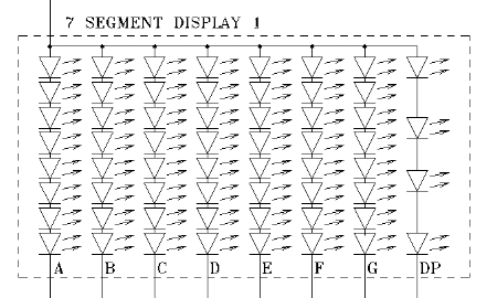
Is it just for Neo?No of course not, why should Neo have the matrix control all to himself? Yes ok, it is a bit of a different matrix that I'm talking about here. This page (and it's contained links) covers everything you wanted to know about a matrix system but were afraid to ask. It's possible to follow and use, all the explanations and examples given on this page(s) and develop a fully operational multiplexed matrix control system*. * I am making the assumption that you have the relevant PLC programming software and hardware (GX Developer & SC-09 lead), as the example matrix control system information I am presenting here uses a Mitsubishi FX2N PLC. A matrix control system is sometimes called a multiplex or multiplexed matrix control system. I've even heard multiplexer matrix control system as well. But don't sweat it, it's all the same thing. I will say the matrix bit makes reference to how the output drive circuitry looks in a circuit diagram. As for the multiplexing, that's how the inputs are expanded into the already set-up output matrix. Clear as mud so far then! Take a step back, it's quite straight forward once you get it. After going through all this I'm laying out for you here, you'll be an expert. We'll be doin' a bit of jargon bustin' too, so you can talk like a pro if you really want to. But at the same time knowing what you're talking about! Anyway so how does a matrix control multiplexed system work? Ok then I'll try and keep the explanation as brief and concise as I can but I don't want to miss anything out and leave you wanting! Alrighty, what an' where shall we kick off with then? How about with what exactly one of these matrix control multiplexed systems is! A matrix control system is a method of generating lots more inputs and outputs from a PLC (or PC) by clever use of the ones that exist. Realising there are advantages to this, I'm sad to say there are also some disadvantages of course. Not every application can use, or is even suited to, a matrix control multiplex system. Speed is a factor here as the inputs and outputs are read and updated in a sequential format, systems that require very fast operation can't use this type of system control. There's not much point trying to implement a matrix system if the PLC or PC does not have enough outputs to start with. As it's the outputs that make it all happen. I would recommend you would need at least 12 outputs to start with to make it worth while. It can be done with less outputs but there's quite a bit of work in the wiring and programming so you have to ask yourself if it's worth it with less outputs. You'll see what I mean by the time you get through this page. So to explain how you get more outputs, if for instance you have just twelve outputs, they would be split into a group of eight and a group of four. Why? Well it's normally done this way for driving seven segment displays... Yes, I know it should be seven and five then, but seven segment displays also have a dot making eight elements. (I assume the dot was added after they were named or it just didn't count for some reason.) Anyway, then you will have two groups of eight and four outputs, the group of eight are called the line data outputs and the group of four are called the line supply outputs. These are so named because a computer byte is eight bits, hence the data outputs being eight lines. The group of four are called the supply outputs because they supply the voltage for the data outputs to switch on.
This may be getting a bit confusing so far, so I'll show you how they are connected with the help of the electrical schematic diagram of one below.
The segments in a seven segment display are labelled 'A' to 'G' and 'dot' or 'DP' for decimal point. That is as you look at the front of it, just like this one to the right here. If we stick with our seven segment display example, the data outputs would connect to the bottom lines. So the data lines would be set to on and off, depending on the number wanted on the display. But our display(s) wouldn't light up until the line supply output was energised, this connects to the common connection at the top left of the diagram. However, what I haven't mentioned so far is that this on/off switching process happens very quickly. So quickly in fact so you can't actually see the on's and off's happening. In fact the favourite frequency for this to happen is at fifty times a second, that's 50Hz as the techy's will know. Incidentally, for PLC or PC outputs to switch at a rate in the order of 50Hz to 100Hz, they have to be transistor type and not relay. Relays just can't operate fast enough, even if they could, they wouldn't last very long, the contacts would wear out. So briefly, having mentioned 50Hz, does that ring a bell at all?
However I do prefer to use a slightly higher frequency of 70-75Hz as this gives an ice cool like glow effect to LED's and seven segment displays, without any visible flicker at all. Unless you normally shake your head about when looking at things! Anyway where was I? Ah yes, LED displays, I better also say that we're are not restricted to displays and LED's. The positive pulsing signal produced (that easily lights an LED display) from a matrix control system, can also be used to switch on and off a relay in the similar manor. With a simple bit of smoothing, like this here below. A diode and a small value capacitor will quite happily keep a relay constantly powered up on a 50Hz pulsed signal without any chatter.
Otherwise things go very weird quickly, take note, I've been there! So to recap, the line supply outputs connect the common of the segments to the positive of the power supply and the line data outputs connect each segment element to the negative of the supply. To calculate how many extra outputs the matrix control will give us, multiply line supply by line data outputs, so 4 x 8 = 32. With the four and eight output split of our example this gives us the possibility of thirty two outputs from twelve, this is a big advantage of course, although there is a bit of a work overhead in wiring and programming. Hmmm, that's all well and good but what if you had forty outputs to start with. That would work out to two hundred and fifty six outputs! 32 supply x 8 data = 256 outputs, not bad at all! Ok consider this then! 20 supply x 20 data = 400 outputs. Wow, an additional bonus! That's really starting to look useful don't you think? Still only 40 outputs to start with too. How cool is a matrix control system now? Now if I were to mention 256 outputs to start with, with 128 supply lines and 128 data lines, 128 x 128 = 16,384. Blows your mind doesn't it! That's starting to look a bit towards, moving pictures display resolution, you will probably recognise the 8, 32, 128 and 265 as closely related to computers numbers, not without reason of course.
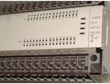
Ok, so that's good for displays and the like but what about matrix control on the machine control front. Let's look at a 64 I/O PLC as a starting point, that gives us 32 inputs and 32 outputs directly. This particular PLC is a Mitsubishi FX2N-64MT, it has in total 32 24V DC inputs and 32 24V DC outputs, transistor driven outputs that is. Perfect for controlling a machine of up to a fair I/O size, but if we needed, or just wanted more outputs, we now know what to do. "BUT what about the inputs?" (I hear you say) This is achieved by using a line supply output to power a common set of inputs. With correct programming ('gated reading inputs', more on this in the programming bit) the inputs can be expanded to the number of line supply outputs, multiplied by the number inputs. If need be. Sounds good doesn't it, something for nearly nothing when you consider the cost of a PLC with the amount of inputs and outputs you can gain from a matrix control system. So why doesn't everyone do it? Because, yes, there is a disadvantage and it's speed of operation, a matrix control system can't detect fast pulses at its matrixed inputs. Obviously this is due to the switching nature of the matrix control that makes the whole thing possible. So this control system is not suited to accurate feedback systems, such as register control or types of machine which need to measure detail. Un-matrixed inputs could be used in tandem with a matrix control system of course as a go between. Even un-matrixed interrupt inputs could be used but the scan time of any controlling program would need to be taken into account, especially as a timer interrupt is used for the matrix control to switch the outputs. For normal on/off operating types of machines it is more than capable and of course all the inputs don't have to be matrixed. If an encoder or resolver was required there are special add-on modules for most makes of PLC. So there are work around solutions to a wide variety of situations. But the biggest overhead of a matrix control multiplexed system is the programming side of it. Not just because of the extra inputs/outputs created but also due to the complexity the style of the controlling program tends to take on, this is true whether implemented in a PLC or PC. Unless you can find a skeleton program and schematic drawing for a system already designed, tried and tested? That would be useful wouldn't it? Or at least food for thought! I have built several displays and machine control systems of the matrix control type. They could easily warrant a website on their own, or dedicated just to multiplexing methods and wiring. Through doing this I've designed and built a data enable card to completely eliminate bleed over due to sequential updating delays when controlling from a PC or PLC. Matrix control multiplex programming management is quite a feat, especially from a PLC, but I’ve excelled in that, so I can be your tour guide. This is very beneficial to you because it shortcuts the experimental stage so you can get to grips with your interest or project much quicker. Have a look here to see an electrical schematic diagram of how the transistor outputs and the inputs of a PLC matrix control circuit connect up, in full. Have a good snoop all over the PLC matrix control multiplex circuit then return here, if you're ready for it after that, we'll have a dive into the PLC programming and structuring that's needed for a matrix control system using a PLC.
Go from Matrix Control back to Machine 'In the Box'. Return from Matrix Control to Home.
|

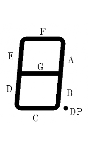 Each segment ('A' to 'G') is an individual LED or group of multiple LED's that light up and are powered as one. But when they are all lit, it looks like this, a number '8' with a dot.
 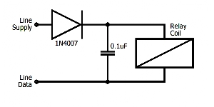 SO, then onwards from the relay, to control whatever your hearts desire. I must stress, to control relays and other output items requiring constant DC, from a matrix control system, does need the smoothing with a diode and small value capacitor though.