|
PLC TUTORIAL
The best PLC tutorial
This electrifying tutorial and associated pages for the
Learn quickly with our PLC Training, help us shape our course(s) to your likeness. The focus of this PLC tutorial is to introduce the PLC to any PLC virgin’s that may be looking with a thirst for knowledge (good for you, nothing to by shy about). Also to those who know a little bit about the PLC, but want to know more about PLC's, how they operate and even how write PLC (basic) Ladder programs.
Read on to find the answers to your questions, questions like; "What's the origins of the PLC?"
"Who invented the PLC and what was the driving force behind it?"
These and the question "Where did PLC's come from?" may be answered by
Also there's the questions like "How PLCs work and what makes a PLC tick."
Also, "What's a PLC tutorial!" AND "What does PLC mean?"
Ok, one question at a time!
- BTW -
So, "What does PLC mean?", that's an easy one (for me) and just in case you missed it at the top of the page.
Let me tell you a story, are you sitting comfortably?
It was during this time that the humble PLC was invented. Way back then, long before computers became common place, pretty much all industrial (or any other) machines were controlled by something called a relay.
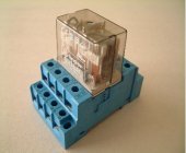
Oh look, just by chance here’s a relay!
Now, no PLC tutorial would be complete which out talking about relays and relay logic! This is because of the way the the program is display looks like an electrical relay circuit.
A relay is an electrically operated switch with one or more contacts that are operated at the same time when an electrical signal is applied to its coil. The coil is an electromagnet which pulls in a hinged metal flapper when operated and mounted on this flapper are the switch contacts.
Before PLCs (and this PLC tutorial, honest) the only way (and/or most efficient way) to make up a control circuit for a machine was with. . . Yep you got it, relays!
As you can imagine, on a machine with many motors and solenoid (posh word for electromagnet) valves to control, would take many relays. All of which had to be wired together in the right order, by following a circuit diagram. I’m glad I didn’t get that job then!
This style of control panel gave rise to several problems, as the relays were mechanical they failed often. Coil failure and contact wear were difficult to diagnose and replace, also if a circuit change was needed that called for a rewired of all the involved relays. A panel with dozens of relays consumed oodles of power.
So one day a smart bloke called Richard E. Morley, an employee of Bedford Associates, invented the first Programmable Logic Controller (Aha PLC) as a consultation project for the General Electric Company in 1968. Bedford Associates changed their name after some time to Modicon PLC and eventually became the supplier of PLCs.
The commercial version didn’t come along until several years later of course, they didn’t have a PLC tutorial in those days of course, so Mr Morley had to make the PLC easy to understand and program for the technicians and maintenance electricians of the day. How did he do that I wonder!
A programmable logic controller (PLC) or programmable controller is a digital computer similar to a PC at its core. It's used for the automation of electromechanical processes, such as machine control systems on factory assembly lines.
The control of almost all types factory machines, in fact but far from just that, the PLC is used also for the control of roller-coaster type amusement rides, escalators, lifts, or lighting fixtures and display panels.
These days PLCs are used in so many different industries and machines. Unlike general-purpose or domestic PC computers, the PLC is designed for multiple inputs and output set-ups, harsh conditions like high (or low) ambient temperature ranges. Built in immunity to electrical noise and very good resistance to impact and vibration. Also resistance to the ingress of water, dust or other contamination such as swarf.
Programs to control machine operation are typically stored in battery-backed RAM (Random Access Memory) or non-volatile RAM. A PLC control system is a real time system since output results are produced in response to given input conditions within a pre-set time limit. So not only are they used for control but also system monitoring as well to prevent unintended operation.
The PLCs operation and hence responses (outputs) to the multitude of conditions (inputs) are pre-set by the program written and uploaded to it by the technician or engineer defining the control systems goals and limitations.
The PLC, an advanced piece of kit, had of course be maintainable by technicians and electrical personnel of the day from many different industries. So, in order to support this, an easy programming language was developed based on the relays and contact symbols technicians were very used to.
Through the relay type wiring diagrams and usual control methods of the normal electrical control panels at that time, all or rather most of the technical bods around could get to grips with the PLC quite quickly. From these early starting years, PLC tutorial and PLC training have developed into a very efficient learning process, even though complexity has gone hand in hand with this.
So the relay programming, or Ladder Logic as it’s now called, schematic style of operation was copied into the PLC programming software. Now would you be surprised to know Ladder Logic is still by far the most popular way to program PLCs today some fifty years later, of course not. But the methods of doing this have changed.
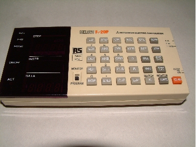
Nowadays PLCs are programmed via a desk computer or laptop, but back then computers weren’t around. The programming of these ingenious devices had to be done with something call a hand-held programmer. These weren’t actually always hand-held, some of them would be clipped onto the front of the PLC itself to program the PLC.
Just like this one here, although it's not that old (only about 20 years) it is very rare now and cannot be purchased any more through the normal channels.
I had this controller as part of my kit for a number of years and just for you I took a picture of it for this PLC tutorial. I don't have it any more though as I thought I'd someone a favor and sold it on Ebay some time ago.
It's immortalized on this PLC tutorial now, this particular programmer is a Mitsubishi F1-20P and to use it you would be entering one relay switch or coil at a time.
Quite laborious as you can imagine, especially if your prospective program is upwards of about 50 steps long (one step is a relay switch or coil). As mentioned, I've used these hand held programmers way back in the past I can tell you with certainty it was difficult as most programs tended to be in the order of the thousands of steps long!
I am completely self taught in PLC programming by learning from the user manuals of various makes of PLC over the years. Mostly using Ladder Logic but also the alternative forms such as SFC and ST programming. I would have loved to have a PLC tutorial to make my job easier then.
Ok, so what does a Ladder Logic program look like then?
Well something like this!
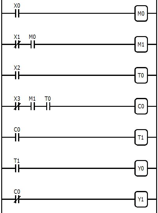
PLC Tutorial Ladder Logic ExampleThis little snippet of ladder program is 17 steps in size, quite small really and it doesn’t do much, but that doesn’t matter as it’s a PLC tutorial example! Even so, it has four inputs (X0 to X3 remember) and two outputs (Y0 and Y1), two internal relays (M0 and M1), also two timers (T0 and T1) and a counter (C0) lurking around in there somewhere.
What is a step I referred to above, a step is the representation of one operation, in other words, one switch (input X0) or one relay coil (output Y0) are one step operations. To start with all PLC program operations were one step operations, as programming advanced multi-step program functions were defined. Data commands like 'MOV A to B' is a two step operation, special module read or write commands can be up to twelve steps using just one command! But, we'll leave that for now, I don't want to give you information overload.
I expect you can easily see why it's called Ladder Logic' now, yep because it look like a ladder. You may also notice how it compares to a relay control circuit diagram. Working from left to right, the supply (+24V DC, 110V AC) would be the vertical bar on the left, followed by the switches, then the relay coils, which connect to the ground (0V or common) return supply, the vertical line on the right.
In a PLC program, the 'X' switches would be the only physical inputs, the other switches and coils would be in the PLCs memory, apart from the 'Y' coils which would be the only physical outputs.
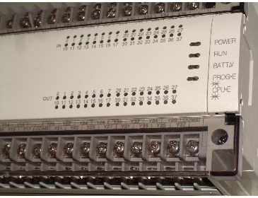
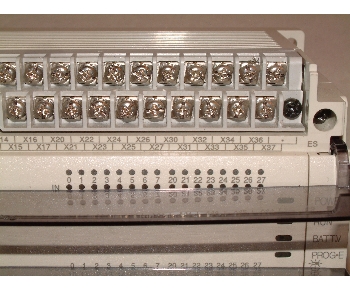
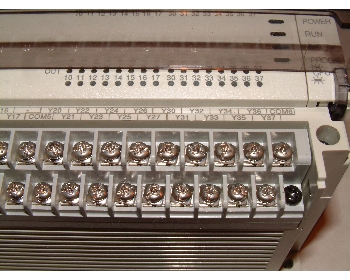
If you had a closer look at the picture on the very top of this page, you can probably make out the 'Y' numbers on the bottom row of terminals. The 'X' numbers are the top row of terminals, but are slightly obscured by the terminal cover, but they are there.
But don't strain your eyes, here they are and I've lifted the terminal covers so you can see them more clearly.
If you look very closely at the numbers you can see they go from X17 to X20 and X27 to X30. What! Can't they count then! Yes, I'm sure they can because the reason behind this numbering mistake is down to how computer data lines are wired.
The PLC computer data lines are wired in multiples of eight, for instance, 'Windows XP 32bit' is operating on four sets of data bus lines. But data lines aren’t numbered one to eight, oh no it's zero to seven, sooo that's...Yep
This is true not just of PLCs in this PLC tutorial, but for all sorts of computers. These days PLCs form the central hub of many manufacturing processes. These microprocessor based boxes of electronics are used everywhere in industry from simple machine projects. Such as one operation box packing machines to the tracking and control of very highly sophisticated, fully automated warehouse systems.
You will find them in virtually all new and most existing manufacturing, processing, printing and packaging machine equipment.
So it won’t surprise you for me to tell you in this PLC tutorial, that because of their popularity being so widespread in industry, it has become increasingly more and more important for technicians to learn the skills needed to use and find fault with these wonderful devices.
OK so now let’s dig a bit further into the guts of a PLC, you’ve come this far I’m sure you’d like to know some more about what make a PLC tick and how PLCs work!
Speaking of ticking, the bit in all of these little beasties that does the ticking is the Microprocessor. The microprocessor or the processor module is the brain in the box, but nowadays microprocessors are a far cry from the 1960’s microprocessors. There is a microprocessor bringing this PLC tutorial to your screen of course.
In essence the job of the microprocessor is to monitor the condition or state of the inputs, use this data in performing the logic of the user program and then update the state of the outputs accordingly. Some PLCs only have as little as 6 inputs and outputs (referred to as I/O) in total to control, but others can have in the order of forty thousand or more I/O.
One single processor is capable of controlling just one process or a whole manufacturing empire, internationally. Quite an easy job when there’s only 6, but when there’s around forty thousand . . . WOW!!! That’s a fast processor.
So it must have somewhere to store the data that represents the inputs status, well yes it does, in memory called RAM.
Also you’ll find some ROM in a PLC, this is Read Only Memory, this is the opposite of RAM, as it’s called a non-volatile memory and it doesn’t lose its data if power is removed. The information held in ROM is burnt into it by a special process and normally contains the operating system of the PLC. Also as the name suggests, the data can only be read from it, not written to it or changed.
Then there will be an amount of EEPROM, this abbreviation means Electrically Erasable Programmable Read Only Memory, aha yes that’s why they’ve abbreviated it then! I’ve forgotten what this memory does . . .
It’s a good job we haven’t run out of memory for this PLC tutorial, otherwise you wouldn’t be reading all this useful info now. Now what else would you like to know as there is much more to see in addition to this tutorial from the PLC page.
If you would like to register to be notified when the;
We at Machine-Information-Systems.com are totally against spam and your information entered on this PLC tutorial page will NEVER be used for any other purpose apart from the "PLC Programming: From the Start" course you're registering for. That's a "cast in stone" promise.
What will the 2020's bring? Only time will tell. 0
Click here now to help shape your PLC tutorial course! Have a look at our FREE PLC Tutorial page.
Go from here to the Technical page.
Return from PLC Tutorial to Home.
PLEASE feel free to use this button and donate You Are Secure!
so Machine-Information-Systems.Com can keep helping you.
|