|
So you want to know about the technical drawing stuff?
Are you sure?
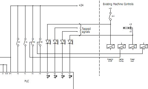
You do!! OK then . . . Now, it would be quite difficult to go into technical drawing and technical writings and keep things generalised. Also I'd probably bore you too tears with ifs and maybes. So what I will do for you is go through the workings of a system that I have designed, built and commissioned into operation. OK yes it was a while ago but the theory of the design holds good, so also do the extra bits the customer wanted as their personal specification. I will put technical drawing snippets into this page in the very near future, so my apologies if the drawings are not there yet. Also I have confirmed it's still in correct operation as of July '06 as I had some feed back about it via an engineer at the factory site. Nothing like a technical drawing revision just an interesting observation, but I asked how it was going, like you do. The reply was all well and good, I was pleased. Before we launch headlong into the technical drawing stuff, let me put you in the picture as to what we’re looking at here. I was charged with building a machine information system for seventeen machines in a box factory. I used small Mitsubishi PLC’s on each machine to gather individual machine data. These PLC’s I called slaves because they were slave to the host system but they were, in fact, programmed as data loggers in their own right. These were all hard wired to the host computer using RS232 ports. Two 8-way RS232 cards were installed into the host computer for connecting all the machines to and I used one of the two existing RS232 ports on the computer. That gave me the seventeen ports needed. It was the customers choice to use a single port for each machine (RS232 serial link can be daisy chained), so the whole system wouldn't fail if a wire was broken/faulty. The technical drawing took me over two weeks as each machine had to have its own specific technical drawing of the connections into its control circuit. The machines weren’t particularly high speed (nor were the operators, hee hee) so there were no technical barriers to break through. ports. Two 8-way RS232 cards were installed into the host computer for connecting all the machines to and I used one of the two existing RS232 ports on the computer. That gave me the seventeen ports needed. It was the customers choice to use a single port for each machine (RS232 serial link can be daisy chained), so the whole system wouldn't fail if a wire was broken/faulty. The technical drawing took me over two weeks as each machine had to have its own specific technical drawing of the connections into its control circuit. The machines weren’t particularly high speed (nor were the operators, hee hee) so there were no technical barriers to break through. Mitsubishi PLC’s were used with RS232 modules and a button panel with an small array of indicators was made for each machine. Button panels! Yes button panels were wanted to give some additional core data into the system. Things like the operator, job start time, job code and a data reset to clear all data before starting a new job. As you might guess the button panels weren’t too technical at all but served a valuable purpose. The purpose of the system was to give the information about which job was on which machine, how long it had been running, when it was due to be completed, which operator was most efficient on a given machine and the more usual stuff like current speed, running or stopped, and machine efficiency. Overview: This was sent via a RS232 line for each machine to the host computer for display. The host computer was dedicated to running the system, as they didn’t want any thing else to interfere with it. The main reason for this was that the host computer was also data logging line for each machine to the host computer for display. The host computer was dedicated to running the system, as they didn’t want any thing else to interfere with it. The main reason for this was that the host computer was also data logging all the total production figures on a daily basis as an operational history of their machines. Right where were we, ah yes. Then the data once on the host computer was displayed in a text style within a formatted window. Also as mention above it was compiled in a spreadsheet file on the local hard drive and sent to a location on the server. These files was updated every minute when new data was received. The file placed on the server was then called up with a remote display program if wanted or loaded into their spreadsheet program for further use within the current office system. The technical writings of data at this point was used for reports and stock control on a continuous basis. The datalogger feature logging to the local hard drive kept the days total accumulated production figures for all the machines in a file with the date in the name. So the following day would automatically rename that days file with the new date so it would not overwrite the previous one. In order to display the days and weeks past production figures within a spreadsheet program another part of the main program produced another file and kept adding each days figures to it. This file just had production data put into it so a picture of the past production could seen within a spreadsheet graph for the last month or quarter. Well that’s about it in a nutshell, Down to the nitty gritty then. The panel lights were there purely to show the operator what was going on within the program at any given stage while pressing buttons. Well, with the exception of one, this one showed when RS232 data was being sent or received. The lights were all controlled from the slave PLC's outputs, more on that soon though. The buttons themselves were wired directly to the inputs on the local slave PLC. Most of the signals used were tapped from existing machine signals so installation was quite straight forward. The client had and supplied me with copies of most of the machines technical drawings which made life quite easy. Technical drawing showing tapped signals from existing machine control.
All the lights and buttons and the slave PLC were operating on the machines 24V DC supply. This addition drew very little current and this kept the system more tidy when installed on the machine(s) than giving it a separate supply, as well as that being unnecessary. There is always some spare capacity in a machines 24V DC control voltage supply, certainly for such a trifling amount of power. Incidentally, the only evidence that there was a system on each machine was of course the HMI panel and the small diameter RS232 cable going away from each machine. I'm currently looking for a suitable technical drawing of the HMI panel to place here to give you an idea of what the HMI panel looks like. (technical drawing of the HMI panel will be here) Right, onwards to the sensor signals used, first there was a running/stopped signal tapped off the machines main run contactor (a contactor is a high current capacity type of switching relay). Then a sensor looking at product going into the machine was tapped off, all but one of the machines had a sensor existing in this position, for its own counter. Handy for me to use of course. At the opposite end of the machine there was a sensor counting the product out of the machine, again most of the machines already had this sensor in place, for those that didn't, a sensor (photocell, what some people call a magic eye) was installed. Quite straight forward to do as it was then dedicated to the machine information system slave PLC. The technical drawing below shows how the sensors and tapped signals were wired to the slave PLC, this is a snippet of the actual customers technical drawing. (MIS_Slave.gif to follow soon) Just one more signal was use from the machines, that was a machine speed signal, all the machines had this signal available somewhere on each machine. This is different from the product signal as it's not dependant on production happening to give the signal. Why machine speed as well as product count? The client was experimenting to try and find the most efficient speed for each machine to run at. Also with a view to streamlining the whole production process to reduce the production bottle neck effect. This may seem like too few signals but that's what was wanted. However, from these signals it was then possible to display the following data on the host display screen. - Machine running or stopped indicator. - Good product. - Waste product. - Production efficiency. - Average production speed per hour (p/h). - Machine speed p/h. - Machine efficiency. - Down time. - Date of last data reset. This data was generated in the slave PLC counting pulses of product and machine operations etc. Once every 30 seconds the host PC would ask all the slave PLC's to send their data, one after the other. This was then sent out via a RS232 module installed in the PLC, down a screened cable to the host PC. Although normally the generation of other data, like efficiency, would be done in the host PC. Because of my fluent PLC programming skills, this was carried out in the slave PLC's to save the overhead on processing in the host display PC. This meant the data sent just have to be displayed or formatted and saved. The result was the system displays performed much quicker on the host PC. How do I know? Because I tried it the other way first. My thinking was to use available resources in the PLC's first to make the system more efficient in it's operation, after all the host display PC may not be dedicated to the system in another application. Now we can leave the technical drawing stuff behind because the data is in the PC. From this point onwards what happens to the data is under the host display program control. Have a look at the USB to RS232 Cable and the USB printer to parallel port converter cable reviews below, here as promised. These are the best ones I've found and I have personally tested them over time!
IO Gear GUC232A USB to RS232 Cable Review. Sabrent USB printer to parallel port converter cable review. Another USB to RS232 converter cable review coming soon. Link to Host Display Program write-up to follow soon. Go to Custom Machine Builder page. Have a little look-see at Electrical connection examples. Return from Technical page to Home.
Note:
PLEASE feel free to use this button and donate You Are Secure! so Machine-Information-Systems.Com can keep helping you.
|