|
RS232 Pinouts
|
| 25 Pin | 9 Pin | Sign | Name | Signal |
|---|---|---|---|---|
| 2 | 3 | TxD | Transmit | PC Out |
| 3 | 2 | RxD | Receive | PC In |
| 4 | 7 | RTS | Req to Send | RTS Flow |
| 5 | 8 | CTS | Clear to Send | CTS Flow |
| 6 | 6 | DSR | Data Set Ready | Ready |
| 7 | 5 | SG | Signal Ground | Common |
| 8 | 1 | CD | Carrier Detect | Modem connected |
| 20 | 4 | DTR | Data Terminal Ready | Ready |
| 22 | 9 | RI | Ring Indicator | Line Ringing |
A bit of serial communications background. (No pun intended ha)
No matter whatever the name and standard, all serial ports are the same, at least from a functional point of view.
Oh my god! What a sweeping statement I'd better get on and explain why, otherwise I'll be swamped with emails from people telling me "NO THEIR NOT".
So, what do I really mean by that then?
Ok, each RS232 serial port, you see, takes the 32 bits (8 and 16 bits in days gone by) your computer exchanges across its data bus then turns them sideways. From a broadside flat advancing line of digital soldiers, into a single file pulse chain like all the soldiers running along one behind another, in single file. This form of communication earns its name “serial” because the individual bits of information are transferred into a long series.
The change marks a significant difference in coding. The bits of parallel data are coded by their position. That is, the designation of bus line they travel down confers value. The position of a bit in a pulse string gives it its value. The later in the string, the more important the bit.
In a perfect world, a single circuit - nothing more than two wires, a signal and a ground. This is all that would be necessary to move this signal from one place to another without further ado. Of course, a perfect world would have also have fairies and other benevolent spirits to help usher the data along and protect it from all the evil imps and energies lurking about trying to debase and disgrace the singular purity of serial transfer.
The world, I’m sorry to say, is not perfect and the world of computers even less so. Many misfortunes can befall the vulnerable serial data bit as it crawls through its connection. One of the bits of data of a full byte of data may go astray, leaving a piece of data with a smaller value on arrival than it had on departure.
A problem akin to shipping alcohol by a courier service operated by dipsomaniacs! Or the opposite case, in the spirit of electronic camaraderie, an otherwise well-meaning signal might adopt a stray bit like a child takes on a kitten.
Only to later discover the miracle of pregnancy and a myriad of errors that ripple through the communications stream, pushing all the bits backward. In either case, the prognosis is not good. With this elementary form of serial communications, one mistaken bit either way, and every byte that follows will be in error.
Establishing reliable serial communications means overcoming these bit error problems and many others as well. Thanks to some digital ingenuity, however, serial communications work and work well – well enough that you and your computer can depend on them.
Signals.
Serial communication is an exchange of signals across a serial interface, RS232, USB etc. These signals involve not just data but also the flow control signals that help keep the data flowing as fast as possible – but not too fast.
The definition of signals.
The names of the signals on the various lines of the serial connector sound odd in today’s PC-orientated lingo because the terminology originated in the communications industry. The names are more relevant to modems and vintage Teletype equipment.
Serial terminology assumes that each end of a connection has a different type of equipment attached to it. One end has the data terminal connected to it. In the good old days when the serial port was developed, a terminal was exactly that. A keyboard and a screen that translated typing into serial signals.
Today a terminal is usually a PC. Now for reasons know but to those few who revel in rolling their tongues across excess syllables, the term Data Terminal Equipment is often substituted. To make matters worse, many discussions talk about DTE devices, which actually means the same thing as “data terminals”.
The other end of the connection has a data set, which corresponds to a modem, surprise surprise. Once again, engineers often substitute the more formal name of Data Communication Equipment or talk about DCE devices.
The distinction between data terminals and data sets (or DTE and DCE devices) is important. Serial communications were originally designed to take place between one DTE and one DCE. The signals used by the system are defined in those terms. Moreover, the types of RS232 serial devices you wish to connect determine the kind of cable you must use.
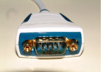
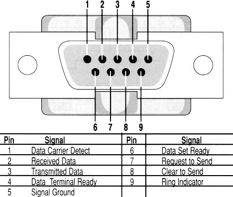
The picture below if the RS232 Pinouts for a standard 9 pin D type connector, D type refers to the shape of the connector itself.
RS232 Pinouts Transmit Data.
The serial data leaving the RS232 port is called the transmit data line, which is usually abbreviated to TxD. The signal on it comprises of the long sequence of pulses generated by the UART in the serial port. The data terminal sends out this signal and the data set listens to it.
RS232 Pinouts Receive Data.
The stream of bits going in the other direction – that is, coming from a distant serial port - goes through the receive data line (usually abbreviated to RxD) to reach the input of the serial ports UART. The data terminal listens on this line for the data signal coming from the data set.
RS232 Pinouts Data Terminal Read.
When the data terminal can take part in communications, that is, it is turned on and I the proper operating mode. It signals its readiness to the data set by applying a positive voltage to the data terminal ready line, which is abbreviated as DTR.
RS232 Pinouts Data Set Ready.
When the data set is able to receive data, that is, it is, it is turned on and I the proper operating mode. It signals its readiness by applying a positive voltage to the data set ready line, which is abbreviated as DSR. Because serial communications must be two way, the data terminal will not send out a data signal unless it sees the DSR signal coming from the data set.
RS232 Pinouts Request To Send.
When the data terminal is on and capable of receiving transmissions, it puts a positive voltage on its request to send line, usually abbreviated RTS. This signal tells the data set that it can send data to the data terminal. The absence of an RTS signal across the serial connection will prevent the data set from sending out serial data. This allows the data terminal to control the flow of data to it.
RS232 Pinouts Clear To Send.
The data set too needs to control the signal flow from the data terminal. The signal it uses is call clear to send, which is abbreviated to CTS. The presence of the CTS in effect tells the data terminal that the coast is clear and the data terminal can blast down the data line. The absence of a CTS signal across the serial connection prevents the data terminal from sending data.
RS232 Pinouts Carrier Detect.
The serial interface standard shows its roots in the communication industry with the carrier detect signal, which is usually abbreviated to CD. This signal gives a modem, the typical data set, a means of signalling to the data terminal that it has made a connection with a distant modem. The signal says that the modem or data set has detected a carrier wave of another modem on the telephone line. In effect, the carrier detect signal gets sent to the data terminal to tell it that communications are possible. In some systems, the data terminal must see the carrier detect signal before it will engage in data exchange. Other systems simply ignore this signal.
RS232 Pinouts Ring Indicator.
Sometimes a data terminal has to get ready to communicate even before the flow of information begins. For example, you might want to switch your communications program into answer mode so it can deal with an incoming call. The designers of the serial port provided such an early warning signal in the form of the ring indicator signal, which is usually abbreviated to RI. When a modem serving as a data set detects ringing voltage – the low frequency, high voltage signal that makes telephone bells ring – on the telephone line to which it’s connected, it activates the RI signal. This alerts the data terminal to what’s going on. Although useful in setting up modem communications, you can regard the ring indicator signal as optional because its absence usually will not prevent the flow of serial data.
RS232 Pinouts Signal Ground.
All the signals used in a serial port need a return path. The signal ground provides this return path. The single ground signal is the common return for all the other signals on the serial interface. Its absence will prevent serial communications entirely. Guess what! It’s normally abbreviated SG.
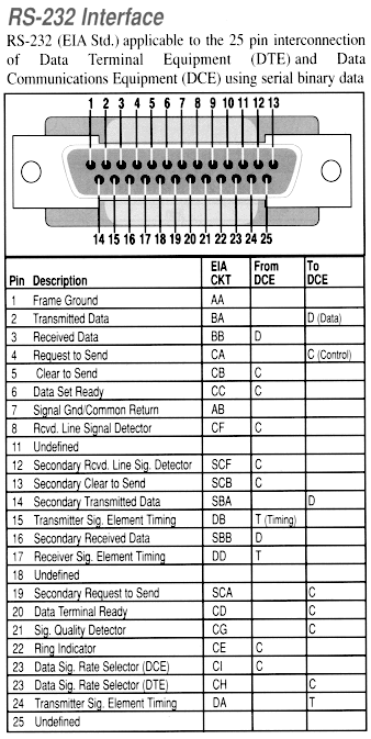
The picture below is the RS232 Pinouts for a standard 25 pin D type connector, D type refers to the shape of the connector itself, as before.
Now you know all about the RS232 pinouts and what the signals are and mean, well done. I'm proud of you for sticking with it.
![]()
I've also done a USB to RS232 cable (USB to RS232 converter cable) review and a USB printer to parallel port converter, click the link below to find them.
Or of course if you prefer, either one of these other links?
Look at the data we'll send through our RS232 pinouts.
Look at the RS232 Wiring formats on this page.
Return from RS232 Pinouts to Home
PLEASE feel free to use this button and donate You Are Secure!
so Machine-Information-Systems.Com can keep helping you.