Electrical
Amps - Volts - Ohms!
Have the Power!
A circuit diagram is essential to find your way around
the machine electrically, it is a blueprint of the electrical interconnections within the machines control circuits.
More electrical/electronic technical drawing and
circuit diagram examples, with short explanations, are being compiled to feature on this page. The purpose of them is to give a pictorial referance as an electrical technical drawing with an explanation of what's going on within it. This helps in getting used to seeing different types of technical drawing (for those that aren't used to them).
For those that are more technically minded, there are some more advanced technical and schematic drawings and techniques being drawn up as well to compliment the more basic stuff. Perhaps they may even give you a new idea or two? Stayed tuned!
* * * * * * * * * * * * * * * * * * * * * * * * * * * * * * * * * * * * * * *
Typical PLC wiring set-up with a 24V DC supply.
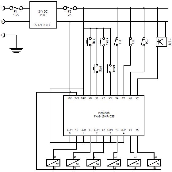
This little electrical circuit shows a typical wiring set-up for a DC supplied PLC, the S/S terminal is a sink or source connection.
The sink or source terminal allows for different types of input sensors to be connected. In this example, the proximity sensor connected to PLC input X7 is a 'PNP' type, it refers to the internal switching transistor type.
This type of sensor supplies 24V DC to the PLC input terminal on being energised. As such the sink/source must be connected to 0V or common to provide a circuit. Of course for the switches, such as the start and reset buttons it's not important whichever way they're connected, but for sensors, it is.
In this case the sensor is a PNP type, the proximity sensor would not work with the PLC sink/source terminal connected to the +24V DC and the supply side of the switches to the 0V DC. Although the buttons would work fine either way.
This is because the output of the PNP electrical sensor signal, when operated, sources (produces) a voltage. This is usually a similar level to the supply positive, maybe less a volt or so.
The difference between the ouptut voltage and the supply is know as the ceiling volt drop. This is known as source or high side switching and is so called as we are switching the higher or more positive supply line.
So to compliment the PNP sensor and also complete the circuit path, the PLC must therefore sink the electrical signal. Of course the complete opposite applies to sink or low side switching. This is so call as you would be switching the lower or more negative supply line.
This basic description will always hold true, but there may be other conditions in more complicated circuits. So bear this in mind when looking at more complex electrical and electronic switching circuits.
* * * * * * * * * * * * * * * * * * * * * * * * * * * * * * * * * * * * * * *
Tapping off existing signals for the PLC.
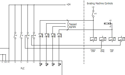
This is an example of how electrical signals can be tapped off from an existing control circuit. The operation signal from top terminal of a control relay (on the right) is fed off through a diode to prevent any back feeding of false signal to the machine control. This relays terminal is a positive 24V DC when the relay is energised and so supplies the PLC input with the same.
The diode is not essential but it is in place as a good practice measure. When a machine is being fault found, engineers introduce signal voltage at various points in the process of investigating a fault. The diode provides separation from the machine and from being joined to another PLC terminal on the machine that may cause a 'lock up' situation, or even damage.
* * * * * * * * * * * * * * * * * * * * * * * * * * * * * * * * * * * * * * *
More examples are being compiled to be added in this section, as this page builds it will provide a useful reference.
Go see the Technical page.See the Definition of Machine/Management Information Systems.
Return from Electrical page to Home
PLEASE feel free to use this button and donate You Are Secure! so Machine-Information-Systems.Com can keep helping you.Are you tired of rising fuel prices!!!
Enjoy this page? Please pay it forward. Here's how...
Would you prefer to share this page with others by linking to it?
- Click on the HTML link code below.
- Copy and paste it, adding a note of your own, into your blog, a Web page, forums, a blog comment,
your Facebook account, or anywhere that someone would find this page valuable.


